
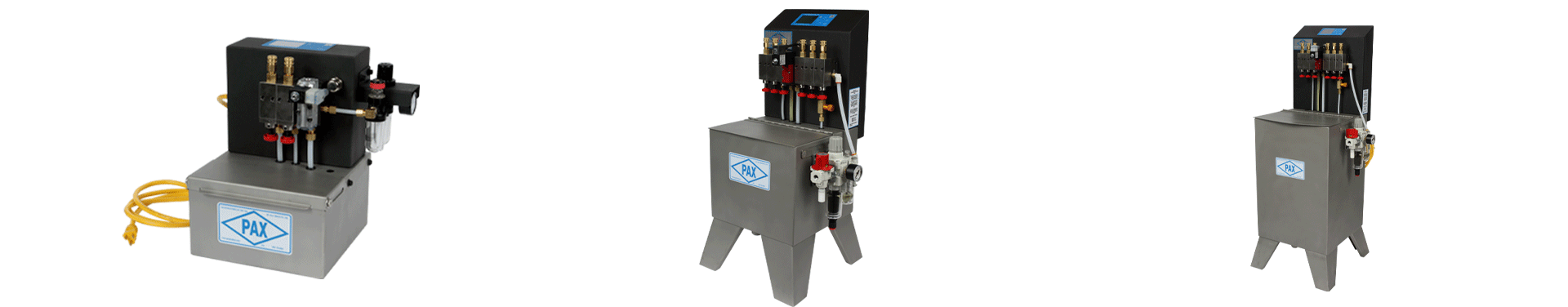
Pre-Pressurized System
Pax is a pioneer of in-die lubrication. The original Pax system was designed and manufactured in 1975 by skilled tool and die craftsmen and tested in our own stamping facility.
By applying only the lubricant needed, only where it is needed, exactly when it is needed, Pax customers have:
- Increased Production Speeds
- Decreased Lube Consumption
- Increased Die Life
- Improved Part Quality
- Improved Working Conditions
All Standard Pax Spray Systems are designed with the following Features:
- “Airless” Spray, which provides better adhesion to the material and less airborne lube than sprays that mix air with the lubricant to better adhere to stock material
- Ability to re-fill system while it’s in operation
- Arranged to promote lubrication recycling
- No Priming Issues
- Customized configurations
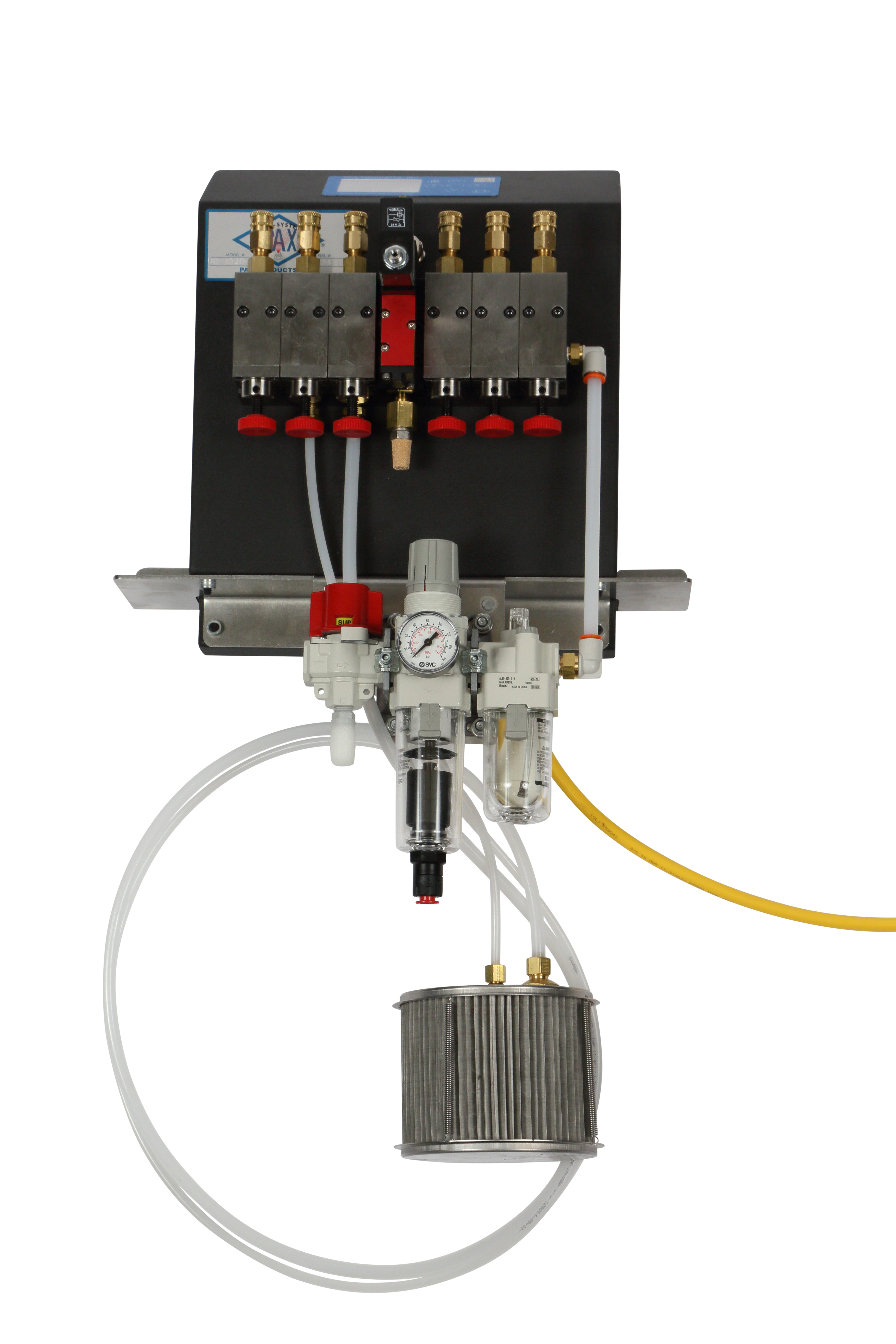
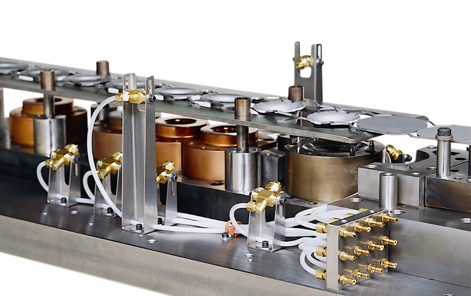
System Overview
How It Works:
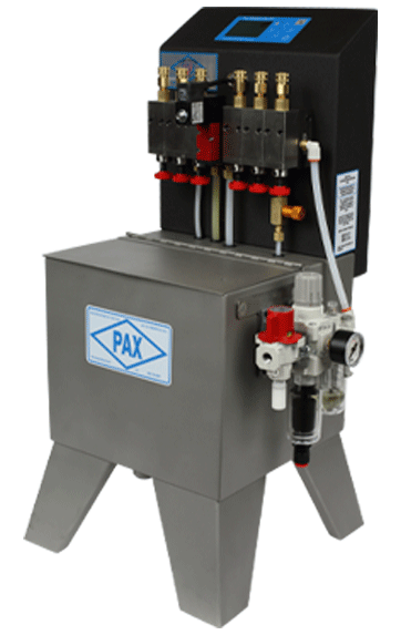
Pre-Pressurized Lubrication Systems utilize a diaphragm pump to provide a consistent supply of pressurized lubricant to each of its distribution pumps. The distribution pumps utilize air-driven pistons with a 10:1 air pressure to lubrication pressure ratio. Each time the distribution pumps cycle, a specific volume of fluid, (based on the volume setting of each pump), is pressurized at the 10:1 ratio and is sprayed onto the die or stock material. The air used to drive the distribution pump is not mixed with the lubricant. A separate distribution pump is utilized to supply lubricant to each individual spray line. This one-to-one arrangement provides the ability for individual volume adjustment and it assures that each nozzle provides an exact amount of lubricant with every spray. The volume of lubricant sprayed by each standard Pax distribution pump can be adjusted between 0.0023 and 0.0210 fluid ounces per spray (0.068 to 0.621 cc) and optional, high-volume distribution pumps are also available.
Ability to Spray Thin and Thick Lubricants:
The 10:1 ratio between the supplied air pressure and the resulting lubrication pressure enables this system to spray both low and high-viscous lubricants.
Note: When the viscosity of the fluid to be sprayed is above 300 SUS, it is important to notify and consult with Pax to assure that the system, the spray nozzles, and the spray lines are correctly configured.
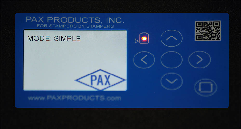
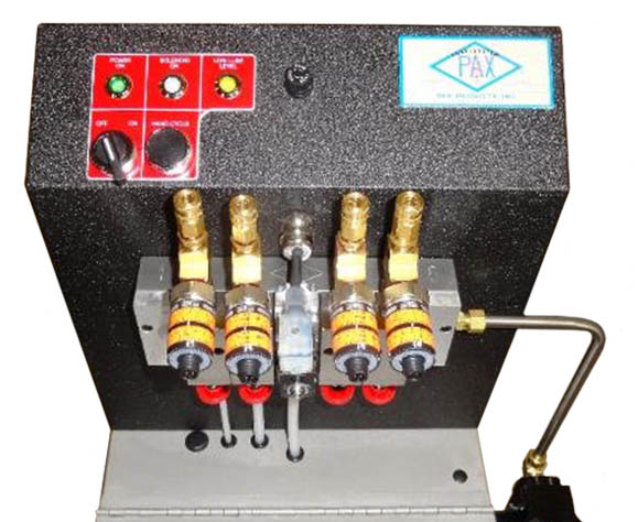
Standard Control:
The Pax Pre-Pressurized system utilizes a PCB membrane switch. The standard functions of this switch include a hand cycle button to manually cycle the unit (this button is in the lower right-hand corner of the keypad) and a low-level indicator light, which will only be active if the unit is equipped with a low-level float, (this indicator is in the upper, left-hand corner of the keypad). Additional functionality is available with the optional advanced control.
This system is arranged for:
- A contact closure, (dry contact), is required to automatically cycle the system.
- Input Power of 115 VAC 60HZ supply OR 24VDC.
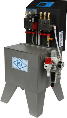
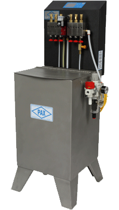
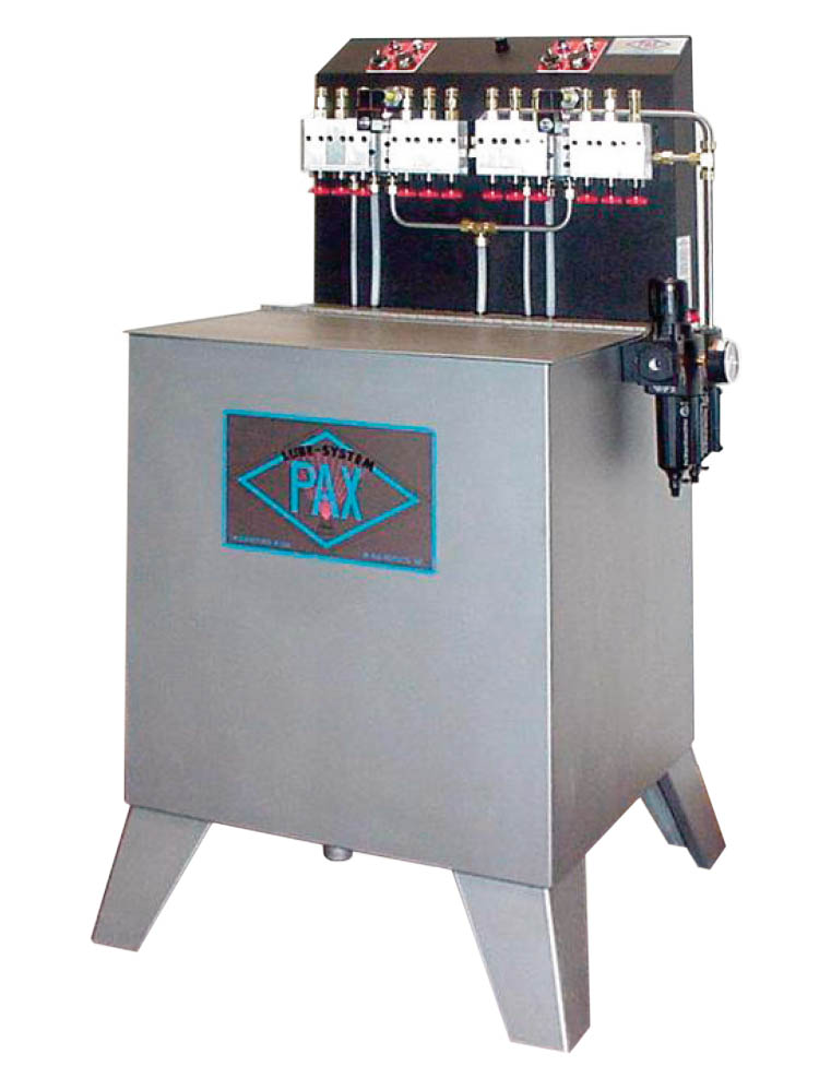
Models with Reservoirs
(Shown with optional Timer and Mounting Bracket)
| Pax Pre-Pressurized Systems with Reservoirs | |||||||
|---|---|---|---|---|---|---|---|
| Model | |||||||
| 2-2 | 5-6 | 15-6 | 15-10 | 30-6 | 30-10 | 30-14 | |
| Number of Distribution Pumps | 1 to 2 | 1 to 6 | 1 to 6 | 1 to 10 | 1 to 6 | 1 to 10 | 1 to 14 |
| Reservoir Capacity | 2 Gallon (7.5 Liter) |
5 Gallon (19 Liter) |
15 Gallon (57 Liter) |
30 Gallon (113 Liter) |
|||
| Size (Width x Depth x Height) | 14.5x11x14″ 37x28x36 cm |
17.5x14x28.5″ 45x36x72 cm |
21x17x42″ 53x43x107 cm |
25x22x42″ 63.5x56x107 cm |
|||
| Approximate Weight | 24 Lbs. 11 kg |
50 Lbs. 23 kg |
80 Lbs. 36 kg |
105 Lbs. 48 kg Max. |
|||
| Lubrication Capacity (Std. Vol.) | .021 oz. (0.62 mil) per Cycle x Number of Pumps | ||||||
| Max. Lubrication Capacity (High Vol.) | .042 oz. (1.24 mil) per Cycle x Number of Pumps | ||||||
| Maximum Cycles/Min. (Full Capacity) | 300 CPM (Higher speeds are possible with reduced spray volume) | ||||||
| Operation Pressure | 30 to 125 psi (205 to 860 kilopascal) | ||||||
| Maximum Air Consumption | .002 scfm per Cycle x Number of Pumps | ||||||
| Voltage | 115 VAC/60 HZ is Standard. Other voltages are available upon request. | ||||||
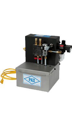
Tankless Models
Pre-Pressurized Tankless Systems
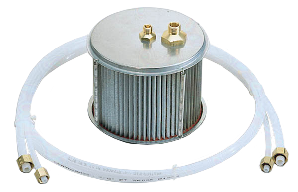
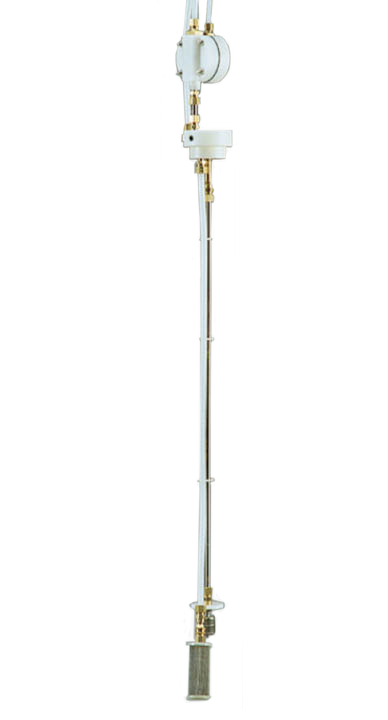
Pax tankless systems can be utilized with central lubrication supply systems or to spray lubrication directly out of the drum or other customer-supplied reservoirs, which requires either a supply pump and filter assembly or a barrel mount supply pump assembly.
| Model 2T | Model 6T | Model 10T | Model 14T | |
|---|---|---|---|---|
| Number of Distribution Pumps | 1 to 2 | 1 to 6 | 1 to 10 | 1 to 14 |
| Max. Lubrication Capacity (Std. Vol.) | .021 oz (0.62 mil) per Cycle x Number of Pumps | |||
| Max. Lubrication Capacity (High Vol.) | .042 oz (1.24 mil) per Cycle x Number of Pumps | |||
| Maximum Cycles/Min. (Full Capacity) | 300 CPM (Higher speeds are possible with reduced spray volume) | |||
| Operation Pressure | 30 to 125 psi (205 to 860 kilopascal) | |||
| Maximum Air Consumption | .002 scfm per Cycle x Number of Pumps | |||
| Voltage | 115 VAC/60 HZ is Standard. Other voltages available upon request | |||
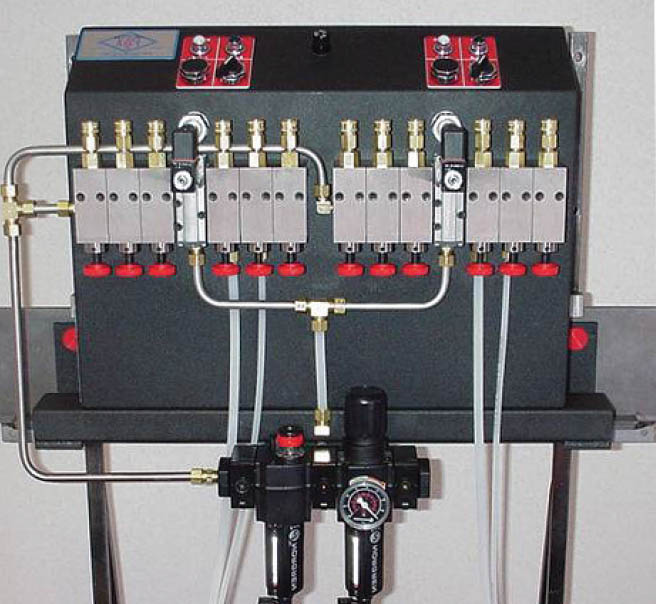
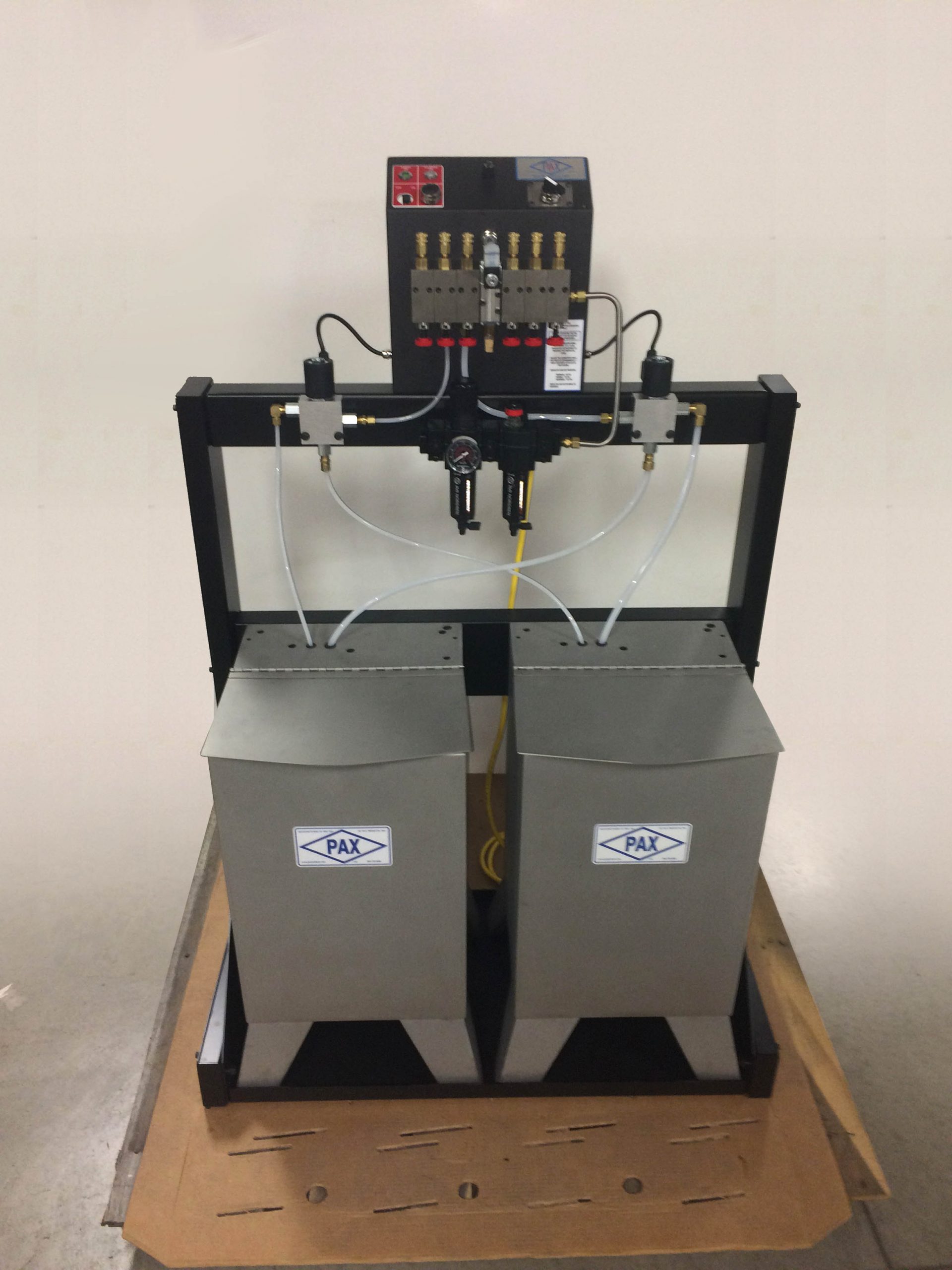
Dual Solenoid & Dual Lube Systems
Dual Solenoid Systems
Multiple solenoid systems provide the ability to independently cycle the different banks of distribution pumps. This is most advantageous for transfer and long-feed progression applications when a certain number of pumps need to be cycled multiple times or at varying times throughout the stroke.
In cases where even greater control flexibility is required, Pax’s V-Series system should be considered.
| Model 6-6T | Model 30-6-6 | ||
|---|---|---|---|
| Number of Distribution Pumps | 1 to 12 6/Solenoid |
1 to 12 6/Solenoid |
|
| Reservoir Capacity | Tankless Units Reservoir Not Included |
30 Gallon (113.5 Liter) |
|
| Max. Lubrication Capacity (Std. Vol.) | .021 oz. (0.62 mil) per Cycle x Number of Pumps | ||
| Max. Lubrication Capacity (High Vol.) | .042 oz. (1.24 mil) per Cycle x Number of Pumps | ||
| Maximum Cycles/Min. (Full Capacity) | 300 CPM (higher speeds are possible with reduced spray volume) | ||
| Operation Pressure | 30 to 125 psi (205 to 860 kilopascal) | ||
| Maximum Air Consumption | .002 scfm per Cycle x Number of Pumps | ||
| Voltage | 115 VAC/60 HZ is Standard. Other voltages are available upon request. | ||
Dual Lube Systems
These systems allow the user to select between two different lubricants, which are stored in separate reservoirs. The systems can utilize either a 6T, 10T, or 14T tankless system or a 6-6T, dual solenoid, tankless system in conjunction with any of Pax’s standard reservoirs. Lube selection, which reservoir the system will draw from, can be done via either manual or electronic valves.
Popular System Options
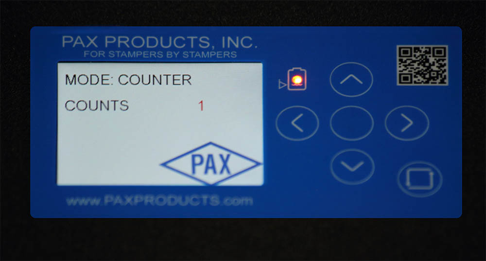
Advanced Control
Based upon the “dry contact” input described in the control description, the advanced control enables the user to cycle the distribution pumps, (regardless of their volume setting), in any of the following methods:
- Simple Mode: 1 spray per cycle, (a cycle is when the dry contact closes and is then re-opened).
- Counter Mode: 1 spray every pre-set number of dry contact closures.
- Timer Mode: System will continuously cycle at a set rate or frequency, (frequency is the number of cycles per second), as long as the dry contact remains closed.
- Multi-Spray Mode: The system provides a specific number of sprays at a set rate or frequency, (frequency is the number of cycles per second), every time the contract closes.
Note: Only one of the above modes can be used at a time and all of the distribution pumps on a standard, single solenoid system will cycle at the same time.
Power Cord and Plug
For the standard 110 V system, a nine-foot power cord with a three-prong plug can be provided.
Air Agitation since
For use with water-soluble lubricants to assure the lubricating medium remains in suspension. A needle valve regulates the amount of air applied to the lubricant reservoir.
Low Level Float
The float switch is designed to connect to the press’ top stop circuit to prevent running the dies dry.


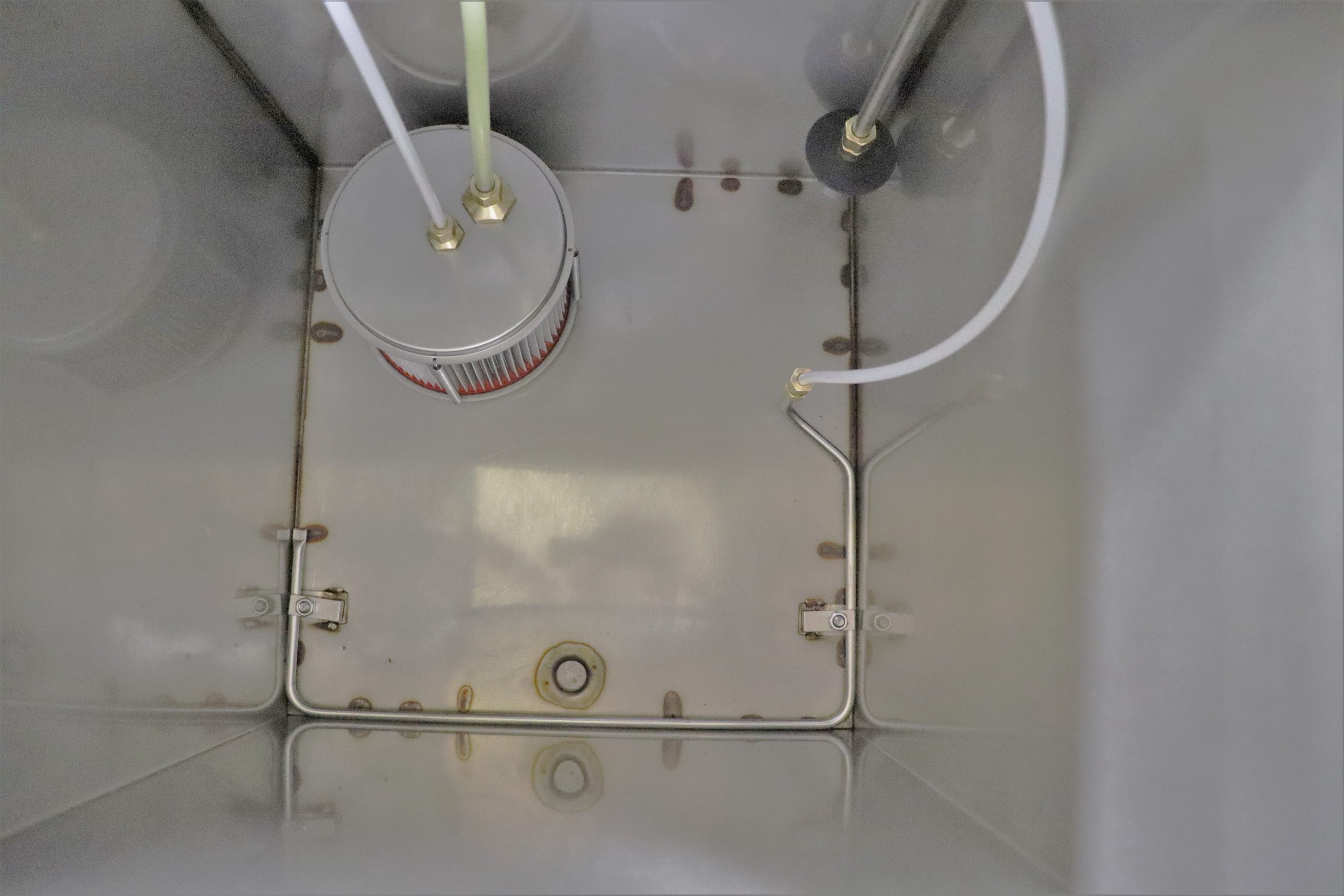
Automatic Refill System:
This system consists of three separate components, listed below, that work in conjunction to maintain fluid in the reservoir.
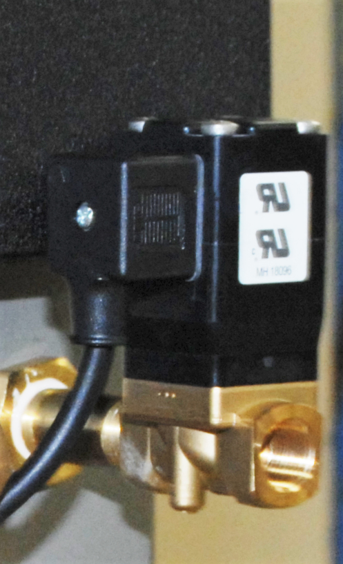
Automatic Refill Solenoid Valve
This valve mounts on the rear of the lube system reservoir and is controlled by the float switches to maintain an adequate supply of lubricant to the system. The valve has a 3/8” NPT (female thread) to which the customer needs to connect their pressurized, lubricant supply. Note: A constant, pressurized lubricant supply must be provided to the valve.
Automatic Refill Floats
A dual float switch system that works in conjunction with the auto refill solenoid valve. These switches open the valve when the fluid is at a level where it needs to be refilled and they close the valve when the reservoir is full.
Low Level Float
This additional float switch detects if the lubrication level in the reservoir goes significantly below the refill level. By interfacing this with the press’s top stop circuit, the customer can stop the press before the reservoir runs out of fluid.
High Volume Distribution Pumps
The volume of lubricant sprayed by each Pax standard distribution pump can be adjusted to provide between 0.0023 and 0.0210 fluid ounces per spray (0.068 to 0.621 cc). This large range has proven to be sufficient for the vast majority of stamping applications. Applications requiring greater amounts of lubricant in a specific area can:
- utilize multiple spray lines to apply lubrication to that area
- utilize a digital timer to cycle the distribution pumps multiple times per stroke (up to a maximum of 300 cycles per minute)
- utilize Pax’s high-volume distribution pumps
Pax’s high volume distribution pumps can be adjusted to provide between 0.0047 and 0.0420 fluid ounces (0.139 to 1.242 cc) of lubricant per spray. But, high-volume pumps have a lower output pressure than Pax’s standard pumps and are therefore not recommended for highly viscous lubricants.
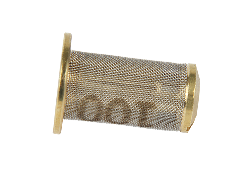
Reservoir Strainer For 5-gallon, 15-gallon & 30 Gallon Systems
This strainer adapts to the lube system reservoir to prevent larger particles from entering the reservoir when fluid is poured into the system. Note: The fluid that enters the system via the return line does not pass through this strainer.
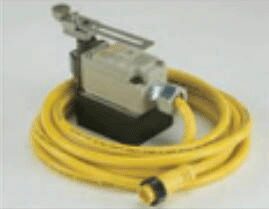
Magnetic Base Limit Switch (P/N 00-1076-32)
This is an arm-type switch mounted on a magnet with a ten-foot cord connecting to a mating connector on a lube system. The arm can be actuated by the press ram or other device to provide the timing signal to the lube system.
Pressure Monitoring Sensors for Spray Lines, (PN 05-1444-30)
This Sensor Assembly is an electronic pressure monitor that allows for the monitoring of a specific spray line of your lubrication system via die protection or PLC integration.
By monitoring the changes in pressure during each spray cycle, the sensor can determine if that line is spraying each cycle. During a spray cycle, the pressure in the spray line rises quickly as fluid is dispensed through the nozzle. After a point in time, the pressure in the spray line reaches a maximum and begins and drops again. When set correctly, the set point pressure of this sensor is triggered when the pressure initially rises during a spray cycle, and the reset point pressure on this sensor is triggered when the pressure decreases. The change of output provided by the sensor as a result of these pressure changes can then be monitored by the customer.
The pressure settings for the switching output of the sensor are controlled via the set and reset point, which is manually set by the user utilizing the orange dials on the sensor. Each Pax spray nozzle has a unique line pressure that is maintained between sprays. The pressure switch must have the set point and reset point above this baseline pressure. Values for the set point, reset point and baseline pressure are subject to each customer’s particular application, cycle speed, and hardware configuration. The switch is capable of monitoring the Pax standard nozzles, high-pressure nozzles, and piston nozzles assemblies. The high-pressure piston requires a higher pressure range and is not suited to this sensor.
The pressure switch utilized is a PNP type sensor that requires a 24 VDC power supply and it provides both normally open and normally closed outputs. Pax will supply a 5-meter long, M12, 4-pin connector cable with each sensor for the customer to utilize for this integration.
Note: It is the customer’s responsibility to provide power to each sensor and to integrate the sensor outputs with either their die protection system or with a PLC as required.

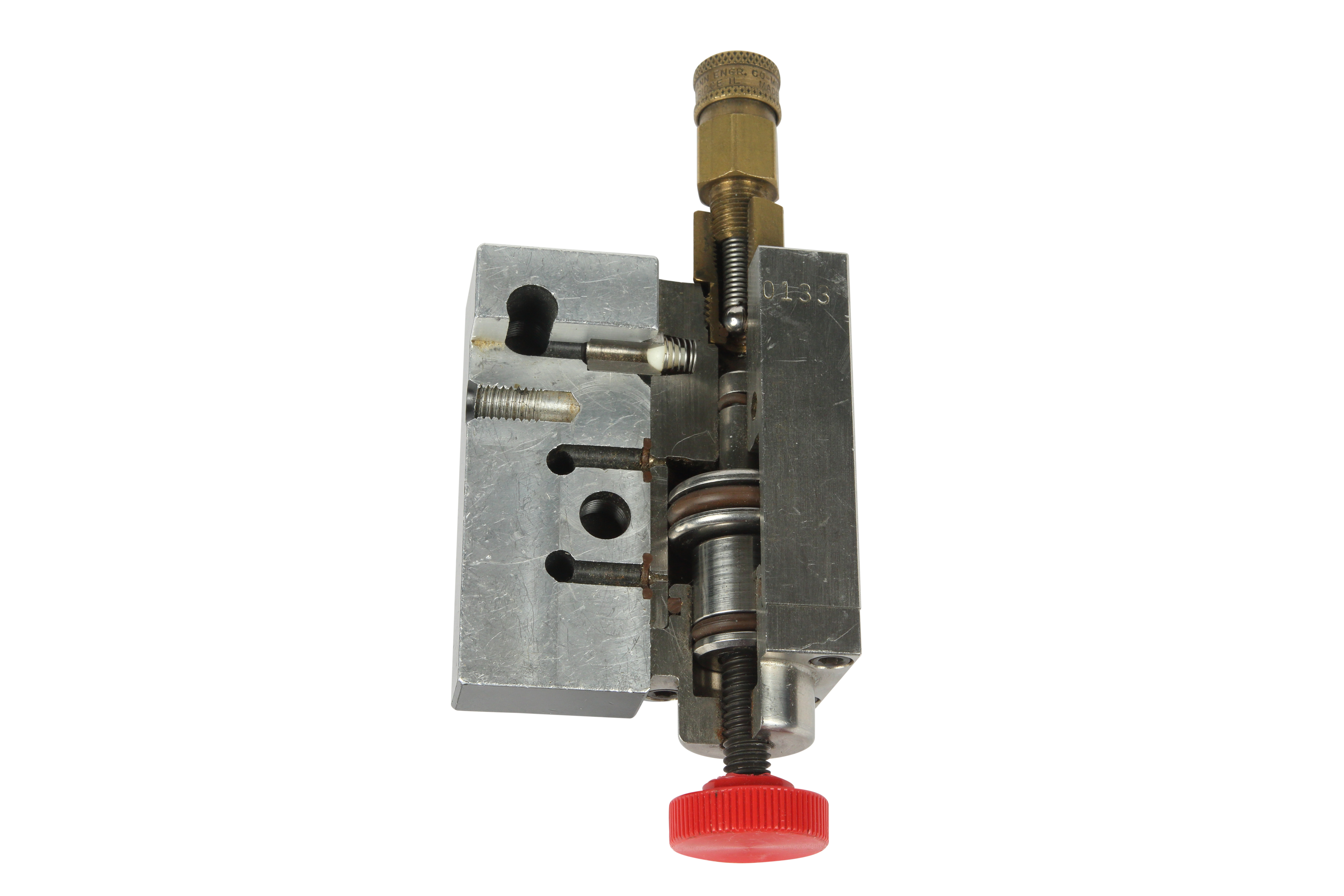
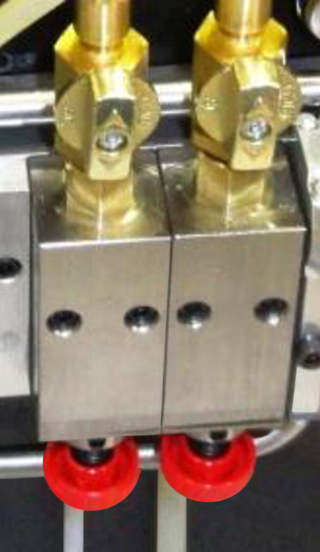
Brass Ball Valves Connected to Distribution Pump Outlet
This arrangement replaces the quick connect fitting typically attached to each distribution pump, which eliminates the flow restriction created by the quick connect arrangement and enables the system to better spray high viscosity lubricant. An unrestricted flow ball valve will be connected to each distribution pump, a compression fitting (P/N 06-0910-20) will be connected to the outlet of the ball valve, and a nylon spray line will be directly connected to the valve via this fitting. The spray line will remain connected to the ball valve at all times and the valve will be utilized to shut off flow to this line when the line is not being utilized.
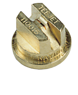
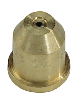
Pre-Pressurized Spray Nozzles
Pre-Pressurized Nozzle Types
High Pressure Nozzle
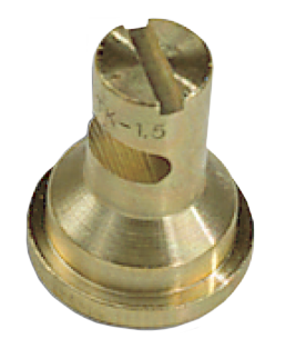
Piston Nozzle

High Pressure Piston Nozzle
| Pax P/N | |
|---|---|
| High Pressure Nozzle with 1/8″ NPT FEMALE Threads | 06-3004-30 |
| High Pressure Nozzle with 1/8″ NPT MALE Threads | 06-3005-30 |
| High Pressure Nozzle with ¼” TUBING Compression Nut & Sleeve | 06-3006-30 |
| Piston Nozzle w/Compression Nut & Sleeve | 06-3100-30 |
| High Pressure Piston Nozzle w/Compression Nut & Sleeve | 06-3144-30 |
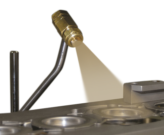
Pre-Pressurized Spray Assemblies
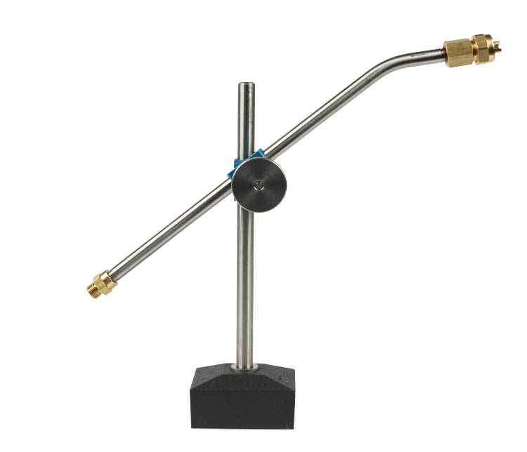
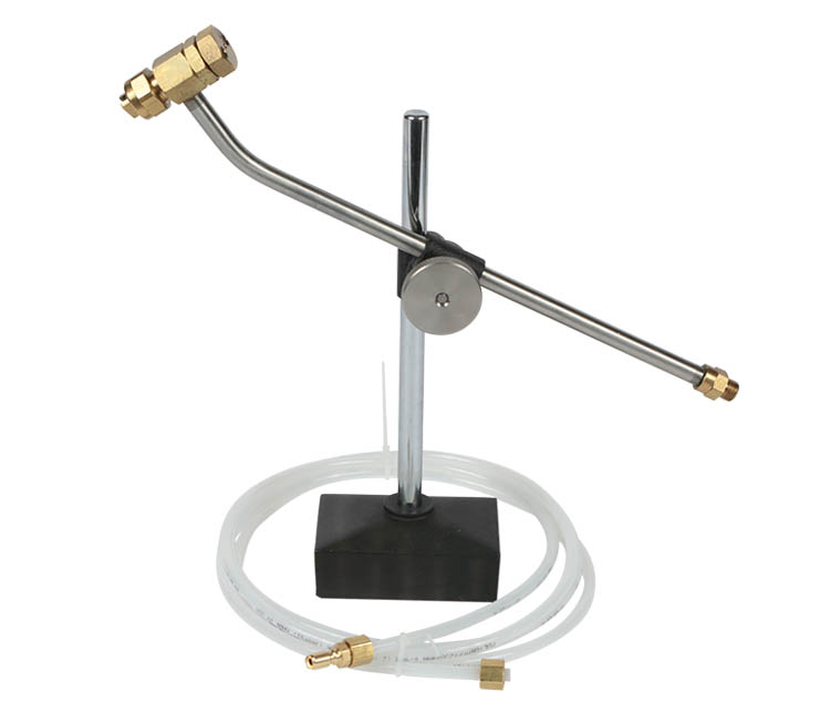
Magnetic Base Spray Assembly for Pre-Pressurized Systems
The magnetic base provides flexibility for positioning the assembly as required and the rigid clamping and spraying assembly assure that the unit remains where it is positioned. The assembly includes a 250 lb. pull magnet with steel post, clamp assembly, stainless steel tube, female nozzle assembly with choice of spray tip, quick connect male plug, and 8′ of ¼ tubing.
| Magnetic Base Spray Assembly Configurations | Pax Part Numbers | ||
|---|---|---|---|
| H.P. Nozzle | Piston Nozzle | H.P. Piston | |
| MBSA w/Soft (Polyethylene) Tubing | 06-3013-31 | 06-3103-31 | N/A |
| MBSA w/Hard (Nylon) Tubing | 06-3014-31 | 06-3104-31 | 06-3149-30 |
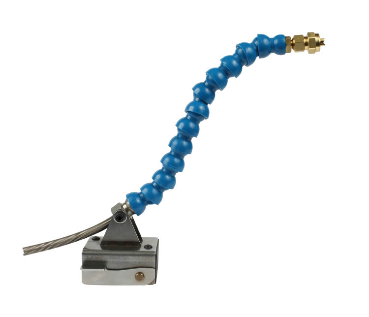
Flextube Magnetic Base Spray Assembly for Pre-Pressurized Systems
The flextube assembly provides ultimate flexibility for the positioning of the spray nozzle, however, it can also be more easily moved out of position than either the magnetic base assembly or the bracket mount assembly. One flextube assembly includes a 250 lb. magnet w/ bracket and release lever, flextube segments, 8’ of ¼” tubing, tubing nozzle assembly, and male plug.
| Flexible Base Spray Assembly Configurations | Pax Part Numbers |
|---|---|
| H.P. Nozzle | |
| Flextube w/Soft (Polyethylene) Tubing | 06-3017-30 |
| Flextube w/Hard (Nylon) Tubing | 06-3018-30 |
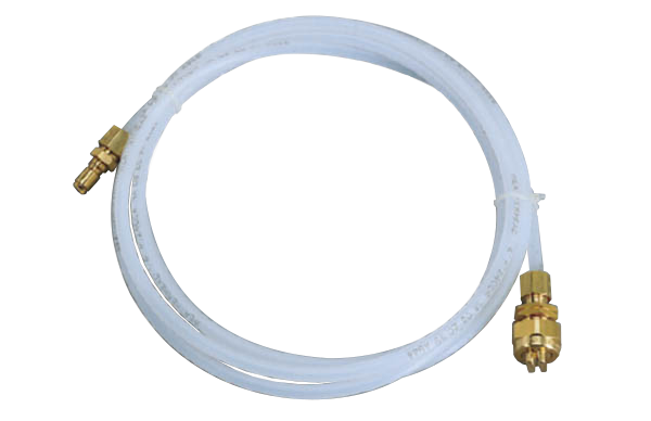
Spray Line Assemblies for Pre-Pressurized Systems
This 8’ long, ¼” spray line has a quick connect male plug on one end, (to connect to the Pax distribution pumps), and a spray nozzle (including nozzle body, check valve, tip retainer, and choice of spray tip) on the other end. The customer is responsible for determining the mounting arrangement.
| Spray Line Configurations | Pax Part Numbers | ||
|---|---|---|---|
| Pre-Pressurized | |||
| H.P. Nozzle | Piston Nozzle | H.P. Piston | |
| Spray Line w/Soft (Polyethylene) Tubing | 06-3009-30 | 06-3102-30 | N/A |
| Spray Line w/Hard (Nylon) Tubing | 06-3010-30 | 06-3101-30 | N/A |
Spray Line Assemblies for Pre-Pressurized Systems
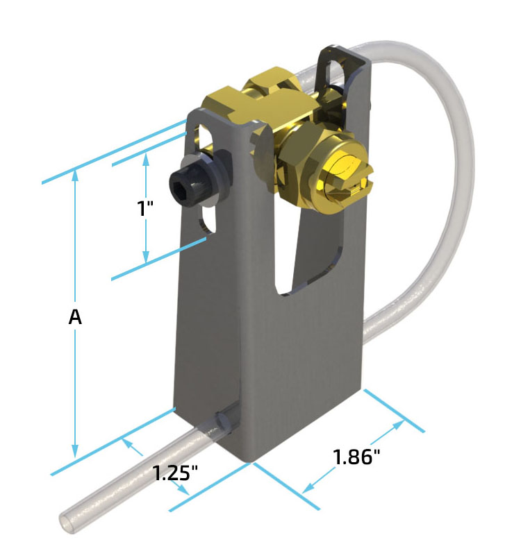
Pax bracket assemblies are the ideal way of permanently mounting spray assemblies. The spray angle can be adjusted by simply rotating either the nozzle and/or the bracket and the vertical height can be adjusted by moving the nozzle within the bracket slot. Once the position of the assembly is finalized, it is locked in place by tightening the bracket screws.
Assemblies include stainless steel bracket, spray nozzle, choice of spray tip, tip retainer, check valve, 1/8″ male elbow, mounting screw, and stainless steel washer. (Requires ¼-20 tapped holes for mounting).
| Bracket Size | A | Pax Part Numbers | ||
|---|---|---|---|---|
| H.P. Nozzle | Piston Nozzle | H.P. Piston | ||
| 1″ to 2″ | 2.45″ | 06-3031-30 | 06-3134-30 | 06-3151-30 |
| 2″ to 3″ | 3.45″ | 06-3032-30 | 06-3135-30 | 06-3152-30 |
| 3″ to 4″ | 4.45″ | 06-3033-30 | 06-3136-30 | 06-3153-30 |
| 4″ to 5″ | 5.45″ | 06-3034-30 | 06-3137-30 | 06-3154-30 |
| 5″ to 6″ | 6.45″ | 06-3035-30 | 06-3138-30 | 06-3155-30 |
| 6″ to 7″ | 7.45″ | 06-3036-30 | 06-3139-30 | 06-3156-30 |
| 7″ to 8″ | 8.45″ | 06-3037-30 | 06-3140-30 | 06-3157-30 |
| 8″ to 9″ | 9.45″ | 06-3038-30 | 06-3141-30 | 06-3158-30 |
| 9″ to 10″ | 10.45″ | 06-3039-30 | 06-3142-30 | 06-3159-30 |
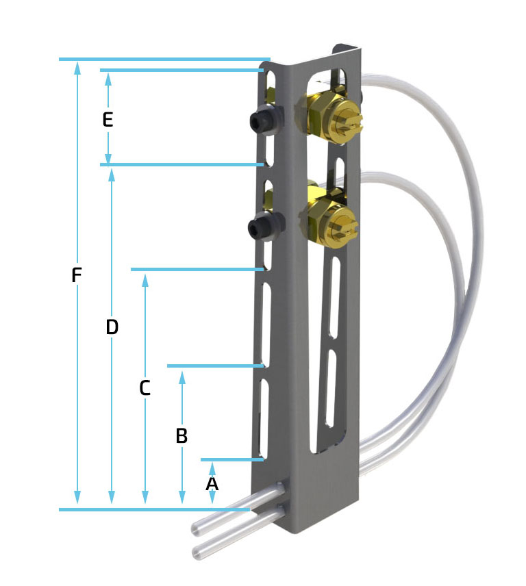
Multi-Nozzle Bracket Mount Assembly for Pre-Pressurized Systems
Includes stainless steel bracket, a mounting screw, a stainless-steel washer, and two of each of the following: spray nozzle, choice of spray tip retainer, check valve, and 1/8″ male elbow. (Requires ¼-20 tapped holes for mounting).
| Bracket Size | Bracket Dimensions | Pax Part Numbers | |||||||
|---|---|---|---|---|---|---|---|---|---|
| A | B | C | D | E | F | H.P. Nozzle | Piston | H.P. Piston | |
| 5″ | 1.5″ | 3.5″ | N/A | N/A | 1.5″ | 5.3″ | 06-3120-30 | 06-3166-30 | 06-3160-30 |
| 6″ | 1.6″ | 3.2″ | 4.9″ | N/A | 1.1″ | 6.3″ | 06-3121-30 | 06-3167-30 | 06-3161-30 |
| 7″ | 1.5″ | 3.5″ | 5.5″ | N/A | 1.5″ | 7.3″ | 06-3122-30 | 06-3168-30 | 06-3162-30 |
| 8″ | 1.7″ | 4.0″ | 6.2″ | N/A | 1.8″ | 8.3″ | 06-3123-30 | 06-3169-30 | 06-3163-30 |
| 9″ | 1.5″ | 3.5″ | 5.5″ | 7.5″ | 1.5″ | 9.3″ | 06-3124-30 | 06-3170-30 | 06-3164-30 |
| 10″ | 1.5″ | 3.7″ | 6.0″ | 8.2″ | 1.8″ | 10.3″ | 06-3125-30 | 06-3171-30 | 06-3165-30 |
Spray Tips (contact Pax for additional tip options)
| Style | Type | Pattern Size | Part No. |
|---|---|---|---|
| Flat | 25° | 1.50″ x 3.50″ | 06-0973-20 |
| Flat | 50° | 2.00″ x 5.75″ | 06-0951-20 |
| Flat | 65° | 2.00″ x 7.50″ | 06-1908-20 |
| Flat | 80° | 2.00″ x 9.50″ | 06-0950-20 |
| Flat | 95° | 2.25″ x 12.00″ | 06-1909-20 |
| Flat | 110° | 2.50″ x 14.00″ | 06-0952-20 |
| Deflected | .041″ Orifice | 4.00″ x 18.00″ | 06-0956-20 |
| Cone | .020″ Orifice | 3.50″ Diameter | 06-0958-20 |
| Cone | .024″ Orifice | 4.25″ Diameter | 06-0953-20 |
| Cone | .030″ Orifice | 5.50″ Diameter | 06-0959-20 |
Note: A low-viscosity (Tellus #10) lubricant was used to obtain the pattern sizes described. The tips were placed in the vertical position and held 6″ from the surface with an air pressure setting on the FRL of 35 psi. Pattern sizes may vary depending on lubricant viscosity and air pressure setting.
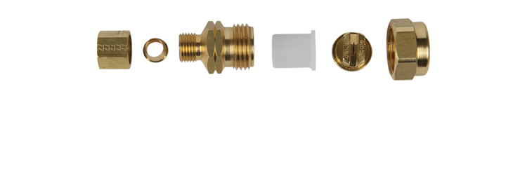
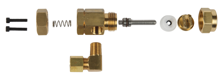
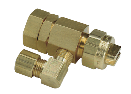
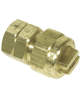
Fittings
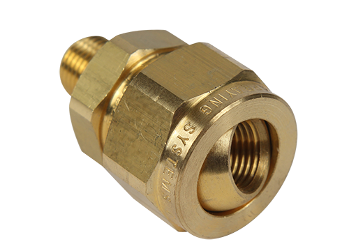
Swivel Adapter
1/8″ MNPT x 1/8″ FNPT
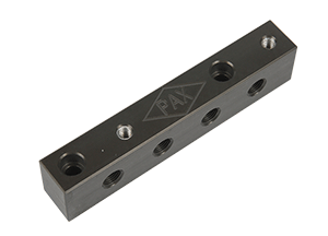
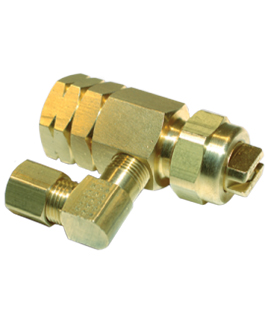
4-Port Stackable Die Manifold
1/8″ FNPT Stackable Manifold
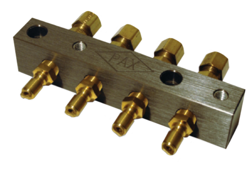
Manifold Assembly
(Provided Unassembled)
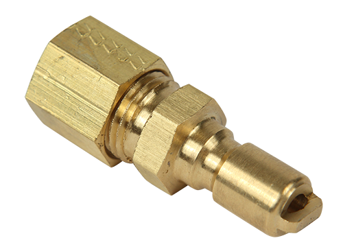
1/4″ Compression
QC Plug
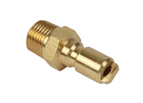
1/8″ MNPT
QC Plug
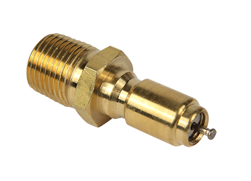
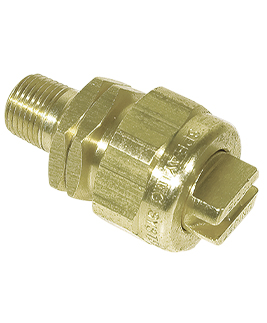
1/8″ MNPT QC Plug
W/ Valve Core
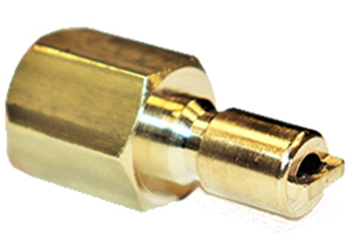
1/8” FNPT
QC Plug
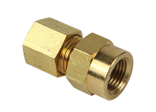
1/4″ x 1/8″
FNPT Compression
1/4″ x 1/8″
MNPT
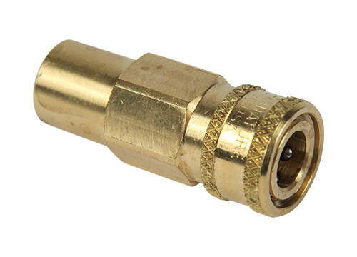
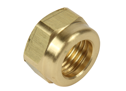
1/8″ FNPT x QC
Coupling
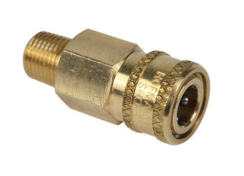
1/8″ MNPT x QC
Coupling
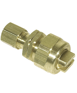
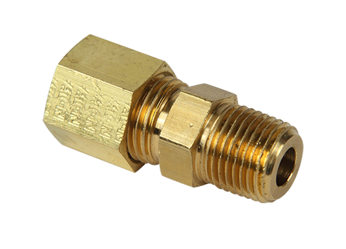
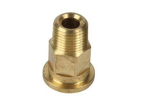
1/4″ Compression x
1/8″ MNPT
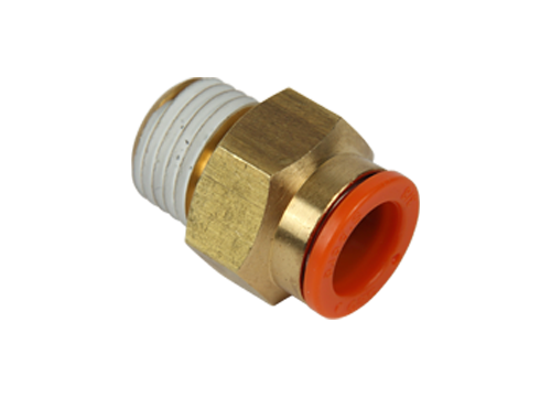
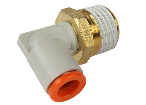
Push To Connect
Straight
Adapter
Fitting
Tip
Retainer
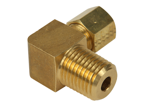
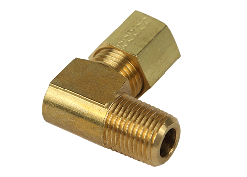
Elbow Compression
Fitting
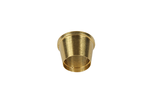
Compression Sleeve
1/4″ Tubing
Standard Check Valve for
V-Series and Original Series
H.P. Check Valve for
Pre-Pressurized Systems
Push To
Connect
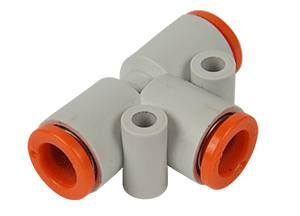
Push To
Connect
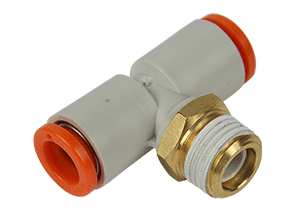
Push To
Connect
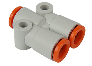
Push To
Connect
MNPT = Male Pipe Thread
FNPT = Female Pipe Thread
QC = Quick Connect
Note: Other fittings are available upon request.