
")


Methods of Applying Lubrication:
In general, lubrication can either be applied to the stock material before the material enters the die or it can be applied after the material enters the die (in this case it could be applied either to the material or directly to the die itself). The most common methods of applying the lubricant to the stock before it enters the die are to utilize either a roller coater or a spray cabinet. In-die lubrication is typically applied by either spraying lubricant into the tooling or by providing lubricant directly into the die itself. All of these methods can be utilized independently or they can be combined to obtain all of the advantages that are listed below.
| Comparison of Roller Coaters & Spray Cabinet to In-Die Lubrication | |
|---|---|
| Advantages of a Roller Coater & Spray Cabinets | Advantages of In-Die Lubrication |
| Typically, this is the easiest way to apply lubricant | Applies lube exactly where required |
| Lubricate both the top & bottom of the stock | Can remove heat and cool tooling |
| Lubrication is contained | Advantageous for long progressive dies that perform drawing or critical forming in their last stations. |
| Excess lubrication can be easily recycled | Can be integrated into the die to assure the exact amount of lubricant is applied exactly where required. |
| Comparison of Roller Coaters to a Spray Cabinet | |
|---|---|
| Advantages of a Roller Coater | Advantages of Spray Cabinets |
| Provides a more even coating on the stock. | Better with galvanized and dirty materials |
| Ability to apply thicker lubricants. | Better for extremely thin materials |
| Compact design makes it easier to integrate | No inherent wear items |
| Less Expensive than a Spray Cabinet | Can apply lube to contoured parts |
Roll Coaters
Roll Coaters
All Pax Roller Coater models include the following features:
- Lubrication is fed through the center of each roll.
- Ability to Provide Different Amounts of Lubricant to Upper & Lower Rolls
- Slim Design
- Increased Roll Life
- Polyethylene spacers, limit the amount of compression on the felt material, which minimizes the material compression.
- Rebuildable Rolls
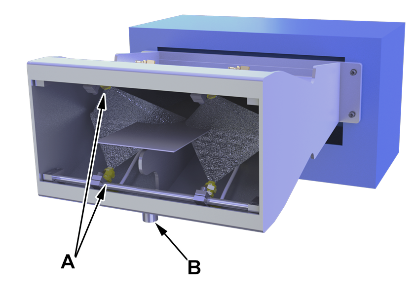
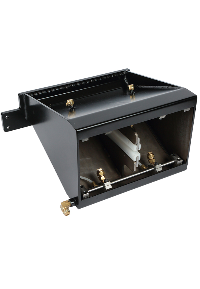
Pax 6″, 9″ & 12″ Roller Coaters
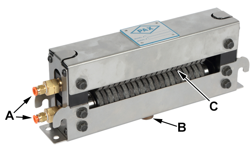
A: Independent Supply to upper & lower rolls.
B: Drain
C: Polyethylene Spacers Minimize Felt Compression & set, which increases roll life.
Pax Roller Coaters 18″ or Greater
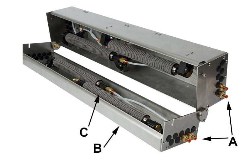
A: Independent Supply to each of the upper & lower rolls.
B: Multiple Upper & Lower Rolls
C: Dual air Cylinders lift and lower each roll
Partially Disassembled Roll
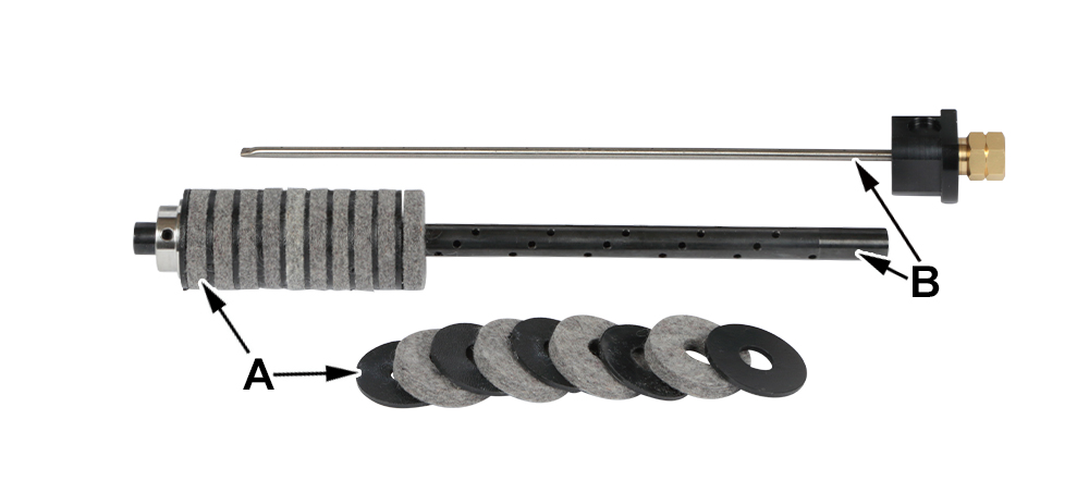
A: The Polyethylene Spacers and Felt Washers can be easily replaced if/when required.
B: Lube is fed through feed tube to the inside of roll axle
| Pax Roller Coater Available Sizes and Specifications | ||||||||
|---|---|---|---|---|---|---|---|---|
| Max Mtl Width | 6″ | 9″ | 12″ | 18″ | 24″ | 30″ | 36″ | 48″ |
| Total # Rolls: | 2 | 2 | 2 | 4 | 4 | 6 | 6 | 8 |
| Dimensions, (Without Fittings, lines, or any options attached) |
11.25″ L | 14.25″ L | 17.25″ L | 29″ L | 35″ L | 41″ L | 47″ L | 59″ L |
| 2.6” deep x 4.75” High (Height is from drain coupling to top of unit) |
Depth at ends is 7.1″, depth for the main body is 6.3″ Height is 15″ (from the bottom of the drain to the top of the air valve) |
|||||||
| Unit Mounting Arrangement (w/o QR Brackets) |
(4) 0.27″ Diameter Clearance Holes 2 Holes on each end are 0.87″ apart. The distance between each set of holes is: |
(4) 3/8″-16 tapped holes on the bottom of the unit. Two tapped holes on each end are 4″ apart. The distance between each set of holes is: |
||||||
| 10.45″ | 13.45″ | 16.45″ | 24″ | 30″ | 36″ | 42″ | 54″ | |
| Quick Release Brkt Mounting |
(1) 0.4″ Diameter Clearance Hole on each end. Distance between holes is: |
Not Applicable | ||||||
| 12.2″ | 15.2″ | 18.2″ | ||||||
| Min. Mtl Thk | 0.02” (steel) | 0.02” (steel) | ||||||
| Max. Mtl Thk | 0.130″ | 0.150″ | ||||||
| Max. Mtl Speed: | 300 fpm | 300 fpm | ||||||
| Upper Roll Pressure: |
Spring Applied. | Two Air Cylinders on Each Roll, Pneumatic applied pressure, spring return. |
||||||
Options for the 6″, 9″ & 12″ Roller Coaters
Optional Entry/Exit Stock Tables for the 6”, 9” & 12” Roller Coaters:
Available Stock Guides can be attached to either or both sides of the Roller
Optional Quick Release Bracket for the 6”, 9” & 12” Roller Coaters:
This bracket enables the user to quickly remove and/or re-install the lube roller. Once the bracket is mounted in place, the lube roller simply slides into the bracket and is held in place by clamps that snap onto the ends of the roller.
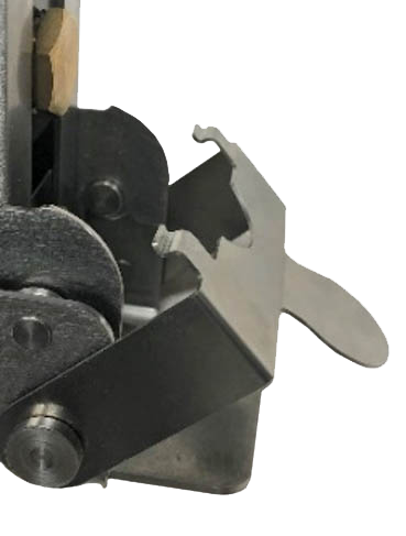
The Roller unit fits into the bracket & the bracket Quick Release clamps hold the roller unit in place.
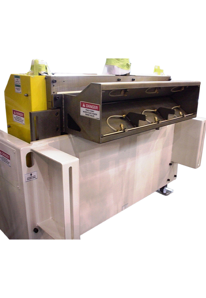
Spray Cabinets
Spray Cabinets
- Sprays, Contains, and Collects Lubricant:
- Non-Contact Lubrication
- Typically attached to, and adjust with roll feeder
A: The material is sprayed from above and below
B: Lubrication recycling port
In-Die Lubrication
In-Die Lubrication:
Goal
The goal of in-die lubrication is to maximize both production and die life by consistently applying the exact amount of lubricant that is required, exactly where it is required. For many applications, this will result in:
- Extended die life, typically by reducing heat.
- Increased production rates
- Reduced quality issues
- Reduced lubricant use
Application Methods
The most typical method of applying in-die lubrication is via magnetic-based spray assemblies, (MBSA). The main advantage of these assemblies is their flexibility, they can be placed pretty much anywhere on the die and can be used on most dies. The main disadvantage of magnetic-based spray assemblies is that they are flexible, which means that they will be set up slightly differently each time they are installed on a specific die, which minimizes consistency.
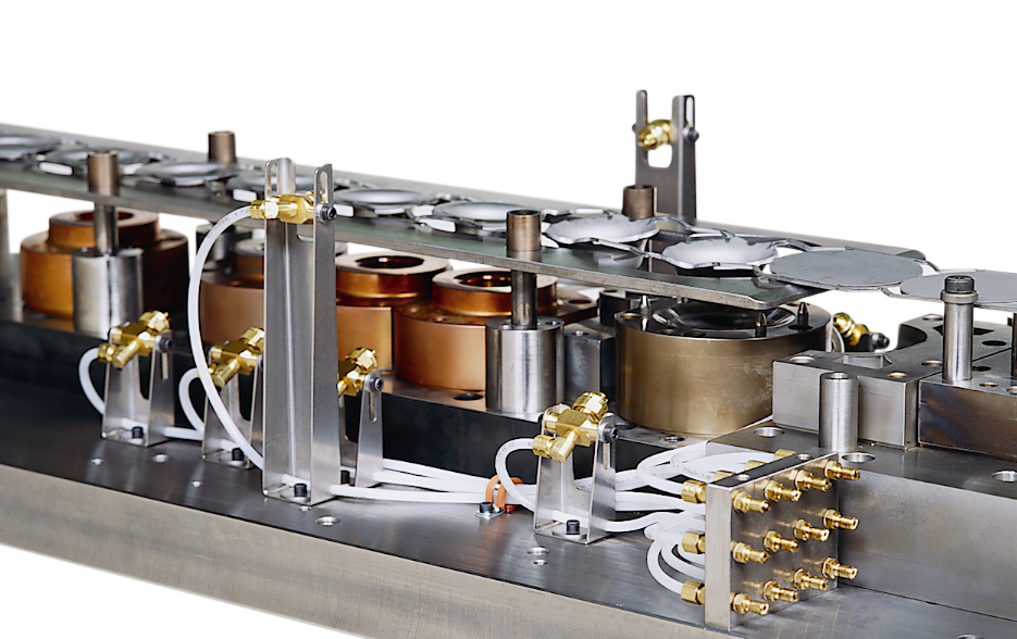
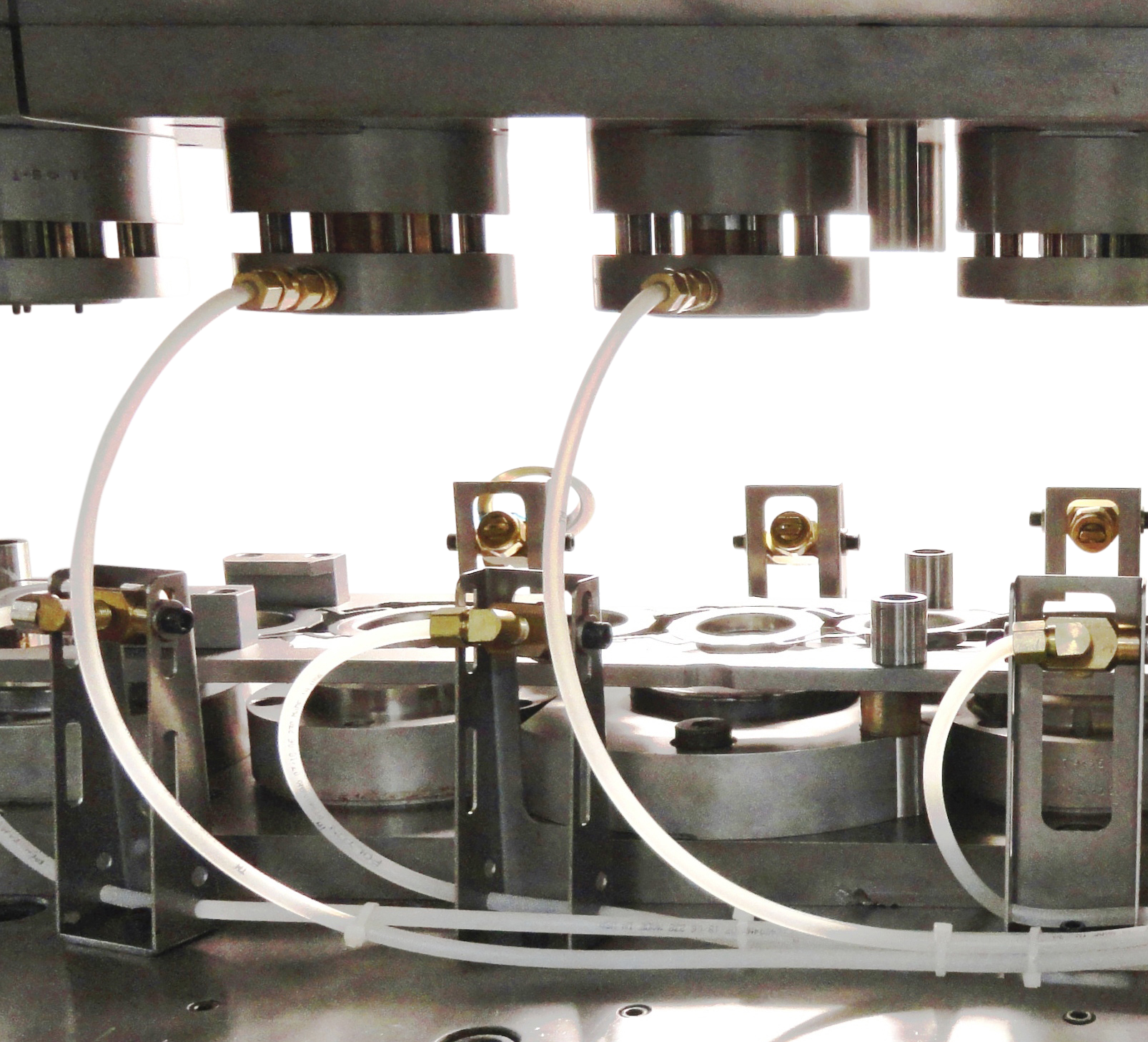
To eliminate the lack of consistency that can result from using magnetic-based spray assemblies, many customers will utilize bracket mount spray assemblies, (BMSA). These nozzle assemblies are bolted directly onto each die. During the installation process, the position and rotation of both the bracket and the nozzle(s) attached to the bracket are adjusted until the lube is applied exactly where it is required. The assembly is then fastened in place to assure that this spray location is maintained.
When it is not feasible to spray lube to the required area via either MBSA or BMSA, it may be possible to either embed nozzles into the tooling or pump lubricant onto, around or through the die punches. This is typically more feasible if it is done when the tooling is initially designed but, in some instances, it is possible to embed nozzles into existing tooling.

Implementation Tips:
- If in-die lubrication methods are to be implemented, it is typically best to start with just one die and to start with either a die that is underperforming or a new die that has not yet been built.
- When feasible, it is typically more advantageous to apply the lubricant to the tooling as opposed to the material. This assures that the lube is applied exactly where required and it can also help to cool the tool.
- Spray nozzles should be positioned as close to the targeted area as possible. This allows the spray system to be run at lower pressure, which will allow the lubricant to better adhere to the targeted area.
- Keep lubrication line length as short as possible and minimize restrictions. This is especially critical for thicker lubricants.
Contact Pax to discuss your specific applications.
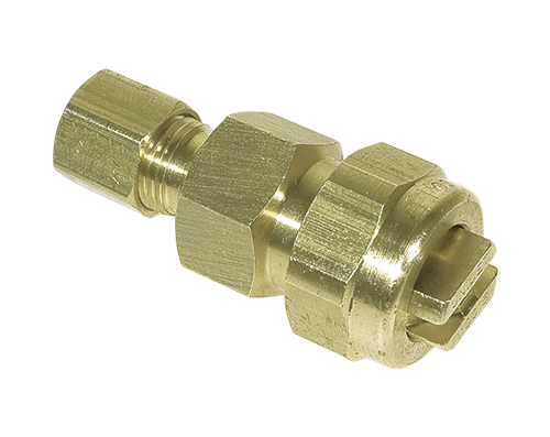
Pre-Pressurized Spray Nozzles
Pre-Pressurized Nozzle Types
High Pressure Nozzle
Piston Nozzle

High Pressure Piston Nozzle
| Pax P/N | |
|---|---|
| High Pressure Nozzle with 1/8″ NPT FEMALE Threads | 06-3004-30 |
| High Pressure Nozzle with 1/8″ NPT MALE Threads | 06-3005-30 |
| High Pressure Nozzle with ¼” TUBING Compression Nut & Sleeve | 06-3006-30 |
| Piston Nozzle w/Compression Nut & Sleeve | 06-3100-30 |
| High Pressure Piston Nozzle w/Compression Nut & Sleeve | 06-3144-30 |
Pre-Pressurized Spray Assemblies
Magnetic Base Spray Assembly for Pre-Pressurized Systems
The magnetic base provides flexibility for positioning the assembly as required and the rigid clamping and spraying assembly assure that the unit remains where it is positioned. The assembly includes a 250 lb. pull magnet with steel post, clamp assembly, stainless steel tube, female nozzle assembly with choice of spray tip, quick connect male plug, and 8′ of ¼ tubing.
| Magnetic Base Spray Assembly Configurations | Pax Part Numbers | ||
|---|---|---|---|
| H.P. Nozzle | Piston Nozzle | H.P. Piston | |
| MBSA w/Soft (Polyethylene) Tubing | 06-3013-31 | 06-3103-31 | N/A |
| MBSA w/Hard (Nylon) Tubing | 06-3014-31 | 06-3104-31 | 06-3149-30 |
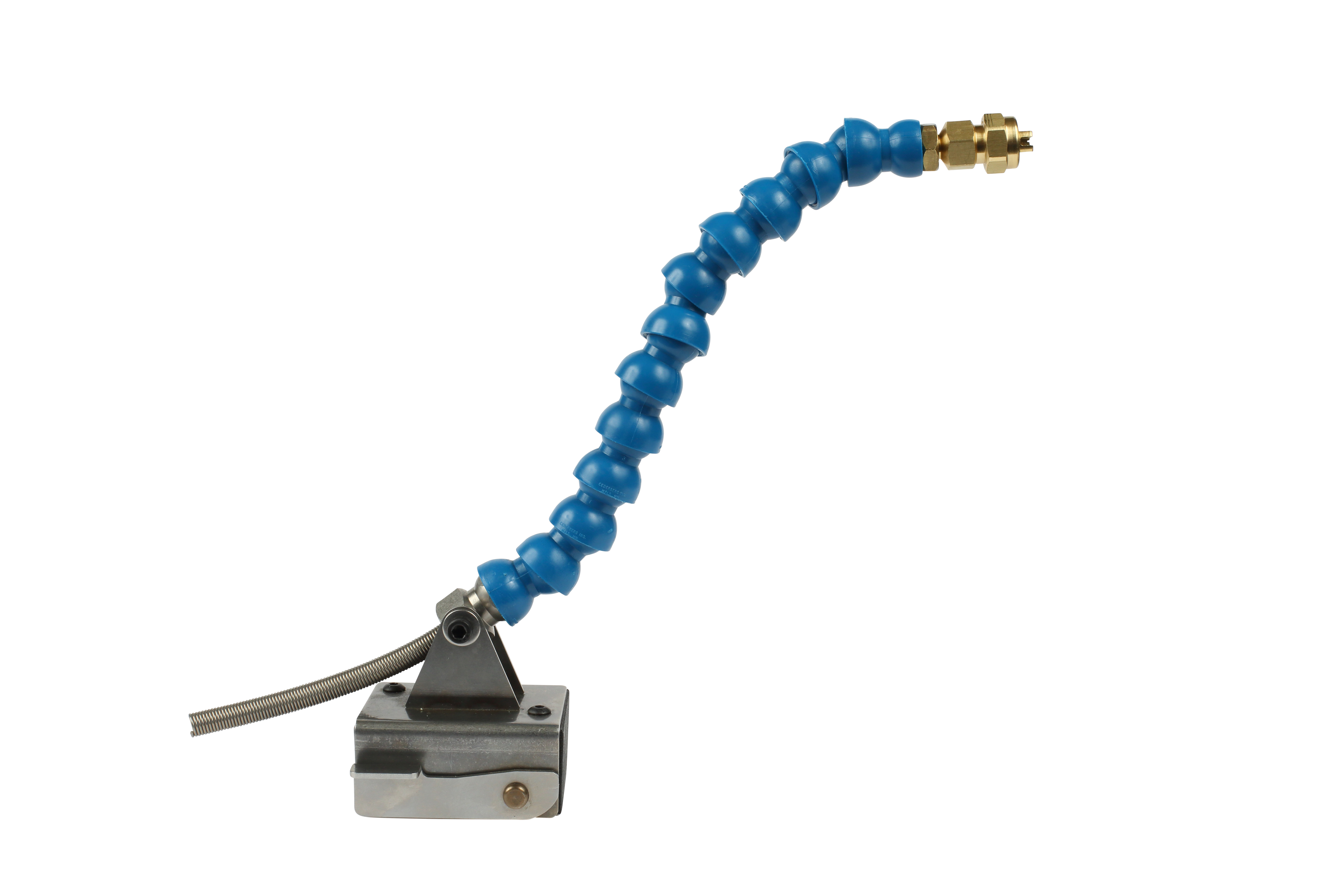
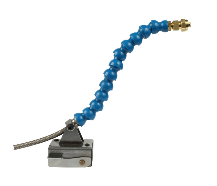
Flextube Magnetic Base Spray Assembly for Pre-Pressurized Systems
The flextube assembly provides ultimate flexibility for the positioning of the spray nozzle, however, it can also be more easily moved out of position than either the magnetic base assembly or the bracket mount assembly. One flextube assembly includes a 250 lb. magnet w/ bracket and release lever, flextube segments, 8’ of ¼” tubing, tubing nozzle assembly, and male plug.
| Flexible Base Spray Assembly Configurations | Pax Part Numbers |
|---|---|
| H.P. Nozzle | |
| Flextube w/Soft (Polyethylene) Tubing | 06-3017-30 |
| Flextube w/Hard (Nylon) Tubing | 06-3018-30 |
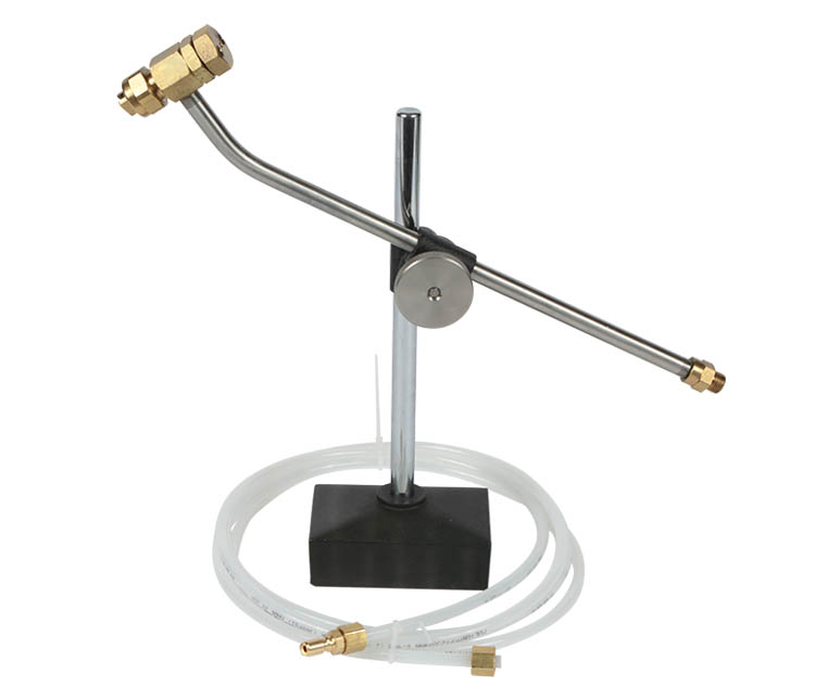
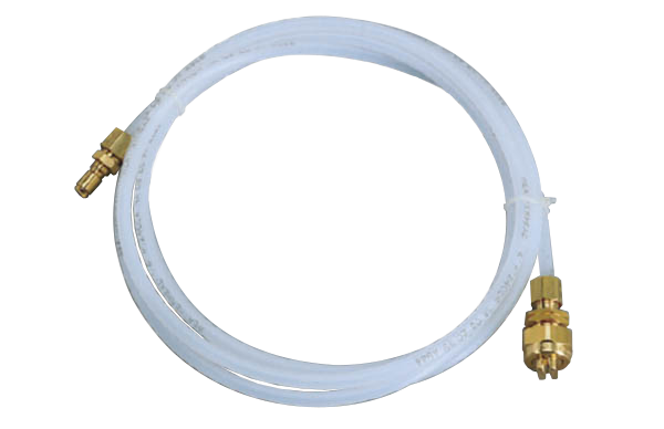
Spray Line Assemblies for Pre-Pressurized Systems
This 8’ long, ¼” spray line has a quick connect male plug on one end, (to connect to the Pax distribution pumps), and a spray nozzle (including nozzle body, check valve, tip retainer, and choice of spray tip) on the other end. The customer is responsible for determining the mounting arrangement.
| Spray Line Configurations | Pax Part Numbers | ||
|---|---|---|---|
| Pre-Pressurized | |||
| H.P. Nozzle | Piston Nozzle | H.P. Piston | |
| Spray Line w/Soft (Polyethylene) Tubing | 06-3009-30 | 06-3102-30 | N/A |
| Spray Line w/Hard (Nylon) Tubing | 06-3010-30 | 06-3101-30 | N/A |
Spray Line Assemblies for Pre-Pressurized Systems
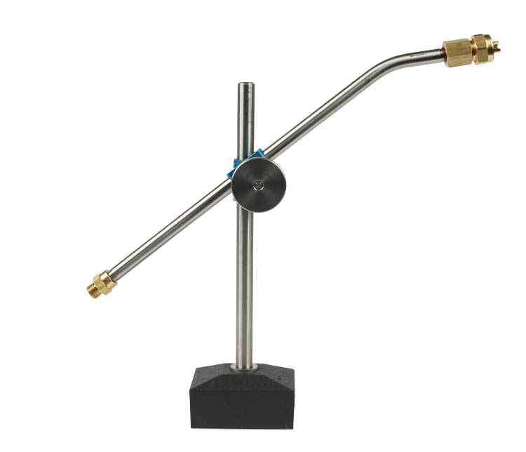
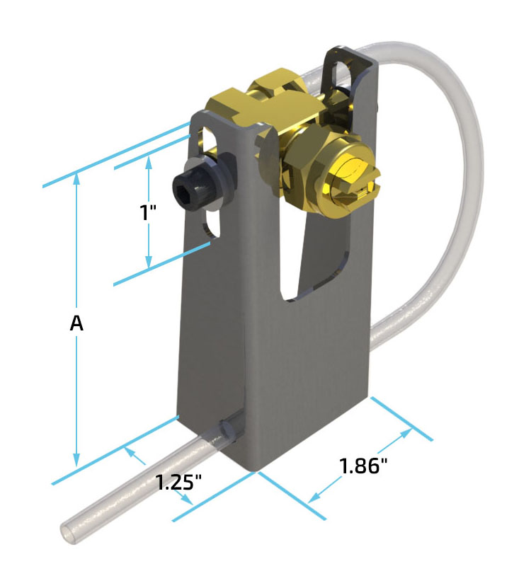
Pax bracket assemblies are the ideal way of permanently mounting spray assemblies. The spray angle can be adjusted by simply rotating either the nozzle and/or the bracket and the vertical height of the nozzle can be adjusted by moving the nozzle within the bracket slot. Once the position of the assembly is finalized, it is locked in place by tightening the bracket screws.
Assemblies include stainless steel bracket, spray nozzle, choice of spray tip, tip retainer, check valve, 1/8″ male elbow, mounting screw, and stainless steel washer. (Requires ¼-20 tapped holes for mounting).
| Bracket Size | A | Pax Part Numbers | ||
|---|---|---|---|---|
| H.P. Nozzle | Piston Nozzle | H.P. Piston | ||
| 1″ to 2″ | 2.45″ | 06-3031-30 | 06-3134-30 | 06-3151-30 |
| 2″ to 3″ | 3.45″ | 06-3032-30 | 06-3135-30 | 06-3152-30 |
| 3″ to 4″ | 4.45″ | 06-3033-30 | 06-3136-30 | 06-3153-30 |
| 4″ to 5″ | 5.45″ | 06-3034-30 | 06-3137-30 | 06-3154-30 |
| 5″ to 6″ | 6.45″ | 06-3035-30 | 06-3138-30 | 06-3155-30 |
| 6″ to 7″ | 7.45″ | 06-3036-30 | 06-3139-30 | 06-3156-30 |
| 7″ to 8″ | 8.45″ | 06-3037-30 | 06-3140-30 | 06-3157-30 |
| 8″ to 9″ | 9.45″ | 06-3038-30 | 06-3141-30 | 06-3158-30 |
| 9″ to 10″ | 10.45″ | 06-3039-30 | 06-3142-30 | 06-3159-30 |
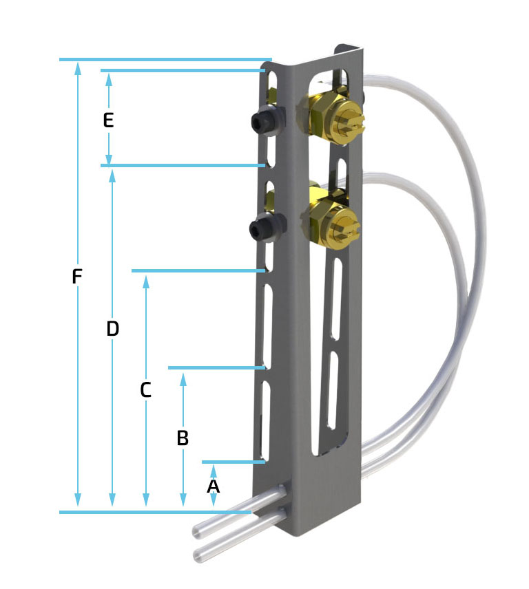
Multi-Nozzle Bracket Mount Assembly for Pre-Pressurized Systems
Includes stainless steel bracket, a mounting screw, a stainless-steel washer, and two of each of the following: spray nozzle, choice of spray tip retainer, check valve, and 1/8″ male elbow. (Requires ¼-20 tapped holes for mounting).
| Bracket Size | Bracket Dimensions | Pax Part Numbers | |||||||
|---|---|---|---|---|---|---|---|---|---|
| A | B | C | D | E | F | H.P. Nozzle | Piston | H.P. Piston | |
| 5″ | 1.5″ | 3.5″ | N/A | N/A | 1.5″ | 5.3″ | 06-3120-30 | 06-3166-30 | 06-3160-30 |
| 6″ | 1.6″ | 3.2″ | 4.9″ | N/A | 1.1″ | 6.3″ | 06-3121-30 | 06-3167-30 | 06-3161-30 |
| 7″ | 1.5″ | 3.5″ | 5.5″ | N/A | 1.5″ | 7.3″ | 06-3122-30 | 06-3168-30 | 06-3162-30 |
| 8″ | 1.7″ | 4.0″ | 6.2″ | N/A | 1.8″ | 8.3″ | 06-3123-30 | 06-3169-30 | 06-3163-30 |
| 9″ | 1.5″ | 3.5″ | 5.5″ | 7.5″ | 1.5″ | 9.3″ | 06-3124-30 | 06-3170-30 | 06-3164-30 |
| 10″ | 1.5″ | 3.7″ | 6.0″ | 8.2″ | 1.8″ | 10.3″ | 06-3125-30 | 06-3171-30 | 06-3165-30 |
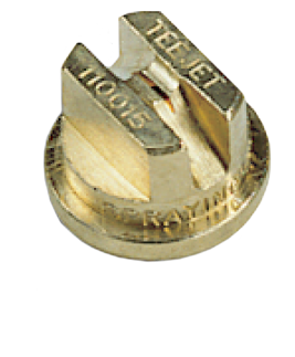
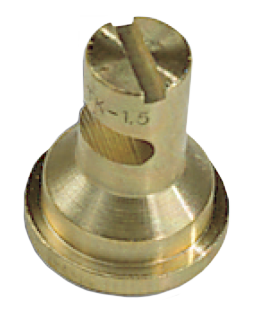
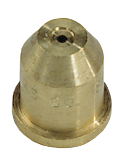
Spray Tips (contact Pax for additional tip options)
| Style | Type | Pattern Size | Part No. |
|---|---|---|---|
| Flat | 25° | 1.50″ x 3.50″ | 06-0973-20 |
| Flat | 50° | 2.00″ x 5.75″ | 06-0951-20 |
| Flat | 65° | 2.00″ x 7.50″ | 06-1908-20 |
| Flat | 80° | 2.00″ x 9.50″ | 06-0950-20 |
| Flat | 95° | 2.25″ x 12.00″ | 06-1909-20 |
| Flat | 110° | 2.50″ x 14.00″ | 06-0952-20 |
| Deflected | .041″ Orifice | 4.00″ x 18.00″ | 06-0956-20 |
| Cone | .020″ Orifice | 3.50″ Diameter | 06-0958-20 |
| Cone | .024″ Orifice | 4.25″ Diameter | 06-0953-20 |
| Cone | .030″ Orifice | 5.50″ Diameter | 06-0959-20 |
Note: A low viscosity (Tellus #10) lubricant was used to obtain the pattern sizes described. The tips were placed in the vertical position and held 6″ from the surface with an air pressure setting on the FRL of 35 psi. Pattern sizes may vary depending on lubricant viscosity and air pressure setting.
V-Series Spray Nozzles
V-Series Spray Nozzles
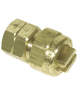
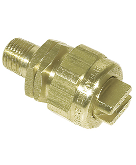
Standard Nozzle for V-Series Systems & Pax Original Style Systems
Std Nozzle with 1/8″ NPT
FEMALE Threads
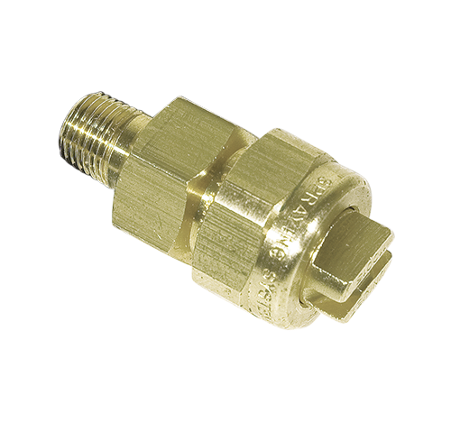
Std Nozzle with 1/8″ NPT
MALE Threads
Std Nozzle with Compression
sleeve and nut for 1/4″ Tubing
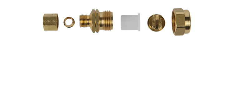
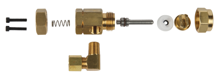
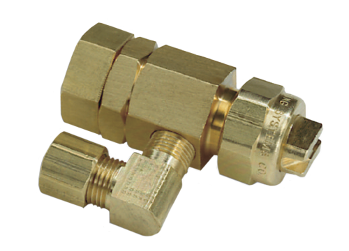
Nozzle Components
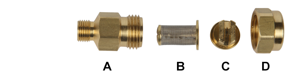
A: Nozzle Body
B: Check Valve Strainer
C: Spray Tip
D: Tip Retainer
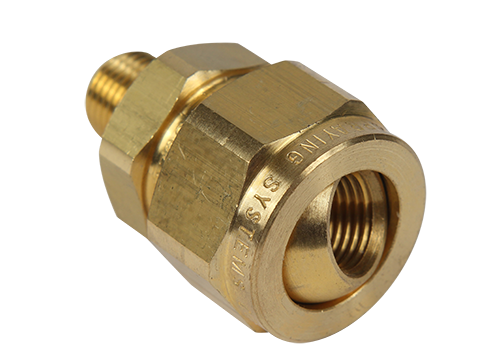
Pre-Pressurized Spray Assemblies
Magnetic Base Spray Assembly with Standard Nozzle (06-3112-31)
The magnetic base provides flexibility for positioning the assembly as required and the rigid clamping and spraying assembly assures that the unit remains where it is positioned. The assembly includes a 250 lb. pull magnet with steel post, clamp assembly, stainless steel tube, female nozzle assembly with choice of spray tip, quick connect male plug, and 8′ of ¼” hard, (nylon), tubing.
Flextube Magnetic Base Spray with Standard Nozzle (06-3016-30)
The flextube assembly provides ultimate flexibility for the positioning of the spray nozzle, however, it can also be more easily moved out of position than either the magnetic base assembly or the bracket mount assembly. One flextube assembly includes a 250 lb. magnet w/bracket and release lever, flextube segments, 8’ of ¼” hard, (nylon), tubing, tubing nozzle assembly, and male plug
Spray Line Assemblies with Standard Nozzle, (06-3012-31)
This 8’ long, ¼” spray line has a quick connect male plug on one end, (to connect to the Pax distribution pumps), and a spray nozzle (including nozzle body, check valve, tip retainer, and choice of spray tip) on the other end. The customer is responsible for determining the mounting arrangement.
Bracket Mount Spray Assemblies for Pax V-Series & Original Style Systems
Pax bracket assemblies are the ideal way of permanently mounting spray assemblies. The spray angle can be adjusted by simply rotating either the nozzle and/or the bracket and the vertical height of the nozzle can be adjusted by moving the nozzle within the bracket slot. Once the position of the assembly is finalized, it is locked in place by tightening the bracket screws.
Assemblies include stainless steel bracket, spray nozzle, choice of spray tip, tip retainer, check valve, 1/8″ male elbow, mounting screw, and stainless steel washer. (Requires ¼-20 tapped holes for mounting).
| Bracket Size | A | Part Numbers |
|---|---|---|
| 1″ to 2″ | 2.45″ | 06-3109-30 |
| 2″ to 3″ | 3.45″ | 06-3110-30 |
| 3″ to 4″ | 4.45″ | 06-3111-30 |
| 4″ to 5″ | 5.45″ | 06-3112-30 |
| 5″ to 6″ | 6.45″ | 06-3113-30 |
| 6″ to 7″ | 7.45″ | 06-3114-30 |
| 7″ to 8″ | 8.45″ | 06-3115-30 |
| 8″ to 9″ | 9.45″ | 06-3116-30 |
| 9″ to 10″ | 10.45″ | 06-3117-30 |
Multi-Nozzle Bracket Mount Assembly for Pax V-Series & Original Style Systems
Includes stainless steel bracket, a mounting screw, a stainless-steel washer, and two of each of the following: spray nozzle, choice of spray tip retainer, check valve, and 1/8″ male elbow. (Requires ¼-20 tapped holes for mounting).
| Bracket Size | Bracket Dimensions | Pax Part Numbers | |||||
|---|---|---|---|---|---|---|---|
| A | B | C | D | E | F | ||
| 5″ | 1.5″ | 3.5″ | N/A | N/A | 1.5″ | 5.3″ | 06-3126-30 |
| 6″ | 1.6″ | 3.2″ | 4.9″ | N/A | 1.1″ | 6.3″ | 06-3127-30 |
| 7″ | 1.5″ | 3.5″ | 5.5″ | N/A | 1.5″ | 7.3″ | 06-3128-30 |
| 8″ | 1.7″ | 4.0″ | 6.2″ | N/A | 1.8″ | 8.3″ | 06-3129-30 |
| 9″ | 1.5″ | 3.5″ | 5.5″ | 7.5″ | 1.5″ | 9.3″ | 06-3130-30 |
| 10″ | 1.5″ | 3.7″ | 6.0″ | 8.2″ | 1.8″ | 10.3″ | 06-3131-30 |
Spray Tips (contact Pax for additional tip options)
| Style | Type | Pattern Size | Part No. |
|---|---|---|---|
| Flat | 25° | 1.50″ x 3.50″ | 06-0973-20 |
| Flat | 50° | 2.00″ x 5.75″ | 06-0951-20 |
| Flat | 65° | 2.00″ x 7.50″ | 06-1908-20 |
| Flat | 80° | 2.00″ x 9.50″ | 06-0950-20 |
| Flat | 95° | 2.25″ x 12.00″ | 06-1909-20 |
| Flat | 110° | 2.50″ x 14.00″ | 06-0952-20 |
| Deflected | .041″ Orifice | 4.00″ x 18.00″ | 06-0956-20 |
| Cone | .020″ Orifice | 3.50″ Diameter | 06-0958-20 |
| Cone | .024″ Orifice | 4.25″ Diameter | 06-0953-20 |
| Cone | .030″ Orifice | 5.50″ Diameter | 06-0959-20 |
Note: A low-viscosity (Tellus #10) lubricant was used to obtain the pattern sizes described. The tips were placed in the vertical position and held 6″ from the surface with an air pressure setting on the FRL of 35 psi. Pattern sizes may vary depending on lubricant viscosity and air pressure setting.
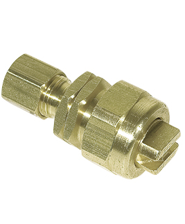
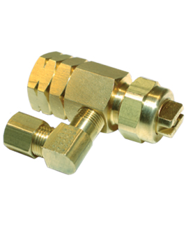
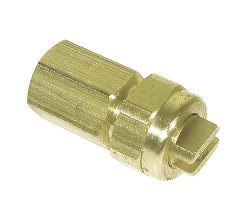
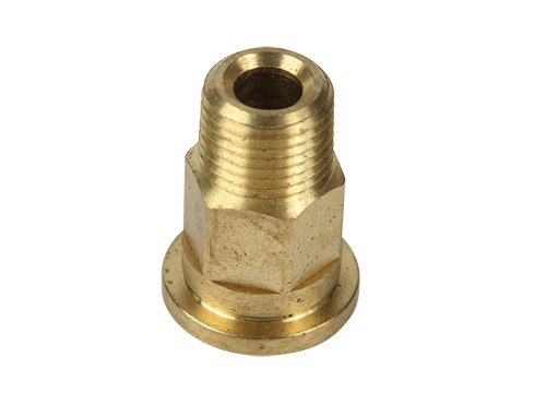
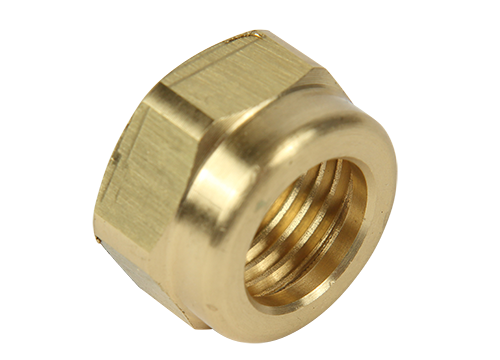
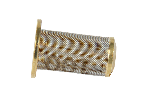
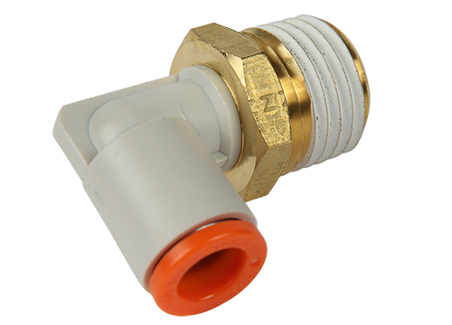
Fittings
Swivel Adapter
1/8″ MNPT x 1/8″ FNPT
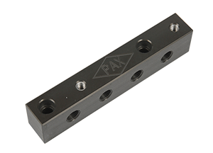
4-Port Stackable Die Manifold
1/8″ FNPT Stackable Manifold
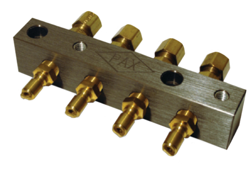
Manifold Assembly
(Provided Unassembled)
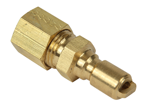
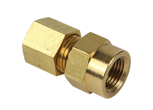
1/4″ Compression
QC Plug
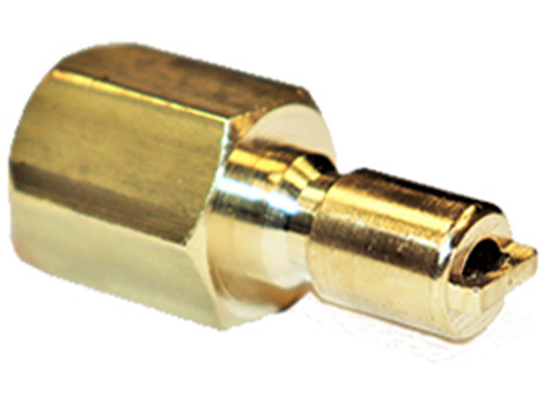
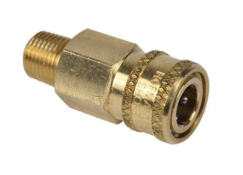
1/8″ MNPT
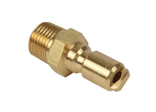
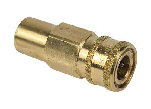
QC Plug
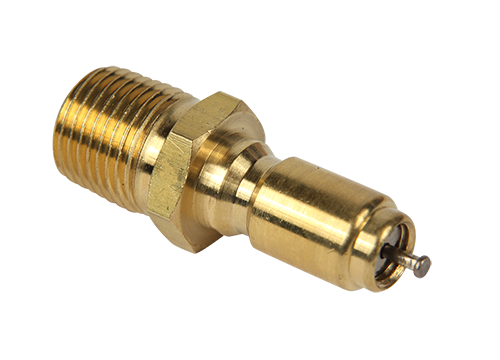
1/8″ MNPT QC Plug
W/ Valve Core
1/8” FNPT
QC Plug
1/4″ x 1/8″
FNPT Compression
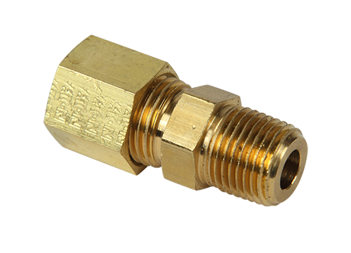
1/4″ x 1/8″
MNPT
1/8″ FNPT x QC
Coupling
1/8″ MNPT x QC
Coupling
1/4″ Compression x
1/8″ MNPT
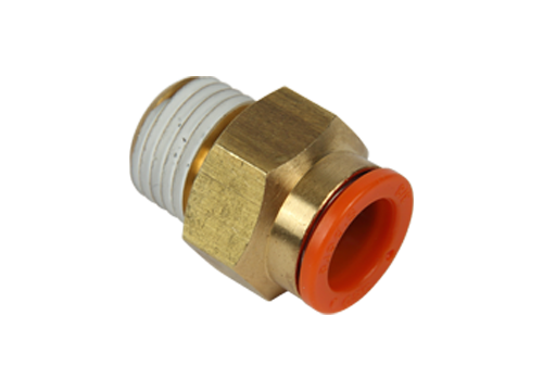
Push To Connect
Straight
Adapter
Fitting
Tip
Retainer
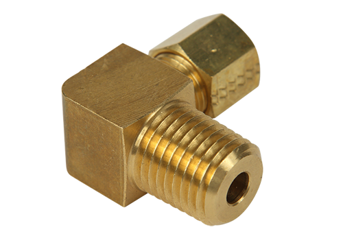
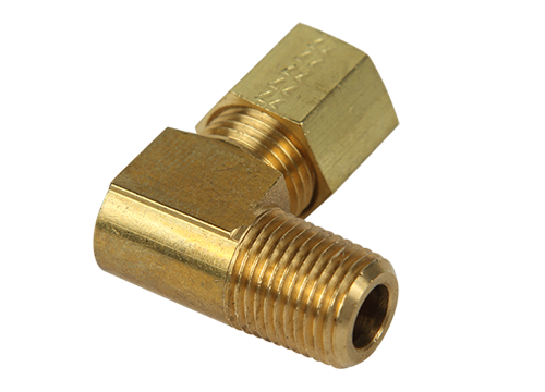
Elbow Compression
Fitting
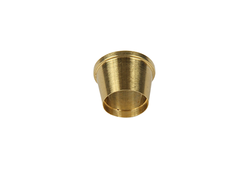
Compression Sleeve
1/4″ Tubing
Standard Check Valve for
V-Series and Original Series
H.P. Check Valve for
Pre-Pressurized Systems
Push To
Connect
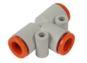
Push To
Connect
Push To
Connect
Push To
Connect
MNPT = Male Pipe Thread
FNPT = Female Pipe Thread
QC = Quick Connect
Note: Other fittings are available upon request.